Category Archives: photonics

Typical silica fiber fabrication process

Typical silica fiber fabrication process

Basically, fiber manufacturers use two methods to fabricate multimode and single mode glass fibers. One method is vapor phase oxidation, and the other method is direct-melt process. In vapor phase oxidation, gaseous metal halide compounds, dopant material, and oxygen are oxidized (burned) to form a white silica powder (SiO2). Manufacturers call SiO2 the soot.

Manufacturers deposit the soot on the surface of a glass substrate (mandrel) or inside a hollow tube by one of the following three methods:

  • Outside Vapor Phase Oxidation (OVPO).
  • Inside Vapor Phase Oxidation (IVPO).
  • Vapor Phase Axial Deposition (VAD).

The soot forms the core and cladding material of the preform. The refractive index of each layer of soot is changed by varying the amount of dopant material being oxidized. Figures 1-3 illustrate the different vapor phase oxidation preform preparation methods.

1

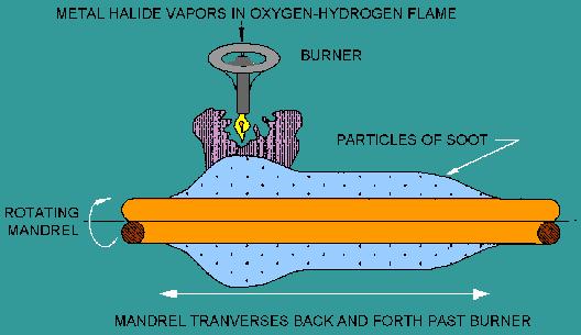
Figure 1. – OVPO preform preparation.

2

Figure 2. – IVPO preform preparation.

3

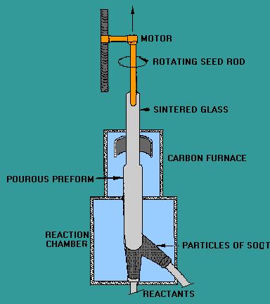
Figure 3. – VAD preform preparation.

During vapor phase oxidation, the mandrel or tube continuously moves from side to side and rotates while soot particles are deposited on the surface. This process forms cylindrical layers of soot on the surface of the mandrel or inside the hollow tube. This deposited material is transformed into a solid glass preform by heating the porous material (without melting).

The solid preform is then drawn or pulled into an optical fiber by a process called fiber drawing.

The fiber drawing process begins by feeding the glass preform into the drawing furnace. The drawing furnace softens the end of the preform to the melting point. Manufacturers then pull the softened preform into a thin glass filament (glass fiber). To protect the bare fiber from contaminants, manufacturers add an acrylate coating in the draw process. The coating protects the bare fiber from contaminants such as atmospheric dust and water vapor. Figure 4 illustrates the process of drawing an optical fiber from the preform.

4

Figure 4. – Fiber drawing process.

To fabricate compound glasses (or sometimes called soft glasses) fibers, direct-melt process, can be used. Multicomponent glass rods form the fiber structure. Rods of multicomponent glass combine in a molten state to form the fiber core and cladding. The double-crucible method is the most common direct-melt process. The double-crucible method combines the molten rods into a single preform using two concentric crucibles.

Optical fibers are drawn from this molten glass using a similar fiber drawing process as in vapor phase oxidation. Figure 5 illustrates the double-crucible drawing process. The drawback of this measure is hard to obtained low loss fibers; this is because melton materials are likely to be contaminated from the inner surface of the crucibles.

5

Figure 5. – Double-crucible fiber drawing process.

[RP photonics Encyclopedia; http://www.rp-photonics.com/fiber_fabrication.html%5D

Dual suspended core optical fibre for sensing application

Dual suspended core optical fibre

Dual suspended core optical fibre was fabricated and demonstrated by researchers at the Optoelectronics Research Centre in the UK. This fibre has unique function that any other fibres not able to achieve easily, not only transmit light, also the two cores can mechanically move and interact with each other. This MEMS-type of optical fibre was made from lead silicate glass.

The submicron optical fibre is highly sensitive to pressure, vibration etc. and would offer interesting applications in the broad field of sensing.


[http://www.osa.org/about_osa/newsroom/newsreleases/2012/new_dynamic_dual-core_optical_fiber_enhances_data/]

Naming Modes

Naming Modes

Detailed discussion and analysis of modal propagation is well outside the scope of this book. However it is useful to understand some of the terminology used in the literature and standard texts. Later it will be seen that multiple modes form in any waveguide situation. This is not limited to fibre propagation but includes, for example, the behavior of light within planar waveguides and within a laser’s cavity etc.

Transverse Electric (TE) Modes

TE modes exist when the electric field is perpendicular to the direction of propagation (the z-direction) but there is a small z-component of the magnetic field. Here most of the magnetic field is also perpendicular to the z-direction but a small z-component exists.
This implies that the wave is not travelling quite straight but is reflecting from the sides of the waveguide. However, this also implies that the “ray” path is meridional (it passes through the centre or axis of the waveguide). It is not circular or skewed.

Transverse Magnetic (TM) Modes

In a TM mode the magnetic field is perpendicular to the direction of propagation (z) but there is a small component of the electric field in this direction. Again this is only a small component of the electric field and most of it is perpendicular to the z-axis.
Rather than talk about field components here it might be better to say that the orientation of the electric field is only a few degrees away from being perpendicular to the z-axis.

Transverse ElectroMagnetic (TEM) Modes

In the TEM mode both the electric and magnetic fields are perpendicular to the z-direction. The TEM mode is the only mode of a single-mode fibre.

Helical (Skew) Modes (HE and EH)

In a fibre, most modes actually travel in a circular path of some kind. In this case components of both magnetic and electric fields are in the z-direction (the direction of propagation). These modes are designated as either HE or EH (H = magnetic) depending on which field contributes the most to the z-direction.

Linearly Polarised (LP) Modes

It turns out that because the RI difference between core and cladding is quite small much can be simplified in the way we look at modes.23 In fibre propagation you can use a single-mode designation to approximate all of the others. Thus TE, TM, HE and EH modes can all be summarised and explained using only a single set of LP modes

http://www.imedea.uib.es/~salvador/coms_optiques/addicional/ibm/ch02/02-13.html

Impact factor 2011, selected Journals

Abbreviated Journal Title (linked to journal information)

Total Cites

Impact Factor

5-Year Impactor Factor

Immediacy Index

Articles

REV MOD PHYS

31368

43.933

44.436

10.026

38

LANCET

158906

38.278

33.797

10.576

276

ADV PHYS

4400

37

25.289

3.778

9

NATURE

526505

36.28

36.235

9.69

841

NAT MATER

39242

32.841

36.732

6.246

134

NAT PHOTONICS

10259

29.278

30.773

5.031

96

NAT NANOTECHNOL

16581

27.27

33.781

5.496

117

NAT CHEM

5260

20.524

20.533

5.308

120

PHYS REP

18742

20.394

20.574

4.6

35

NAT METHODS

15269

19.276

20.454

5.133

128

NAT PHYS

14228

18.967

18.557

5.767

163

MAT SCI ENG R

4487

14.951

16.5

1.75

12

ADV MATER

79860

13.877

12.813

2.155

789

NANO LETT

75287

13.198

13.843

2.082

955

ACS NANO

22409

10.774

11.171

1.631

1141

ADV FUNCT MATER

28503

10.179

9.92

1.514

533

LASER PHYS LETT

4670

9.97

5.927

2.062

145

J AM CHEM SOC

408307

9.907

9.766

1.865

3176

NAT COMMUN

1859

7.396

7.396

1.659

451

LASER PHOTONICS REV

1188

7.388

8.772

2.6

40

PHYS REV LETT

335444

7.37

7.013

2.147

3229

NANO RES

2017

6.97

7.461

0.918

122

NANOMED-NANOTECHNOL

2091

6.692


0.8

110

J PHYS CHEM LETT

4695

6.213

6.217

1.405

529

NANOSCALE

3187

5.914

5.914

1.187

653

LAB CHIP

13729

5.67

6.497

1.143

538

PHYS TODAY

3527

5.648

4.356

1.868

38

MATER TODAY

3452

5.565

10.451

0.482

56

NANOMEDICINE-UK

2103

5.055

6.534

0.87

108

PHYS REV D

120339

4.558

4.027

1.738

2974

NANOTECHNOLOGY

31600

3.979

4.017

0.665

1128

PHYS LETT B

54511

3.955

3.501

2.197

1010

APPL PHYS LETT

203336

3.844

3.787

0.661

4419

PHYS REV B

278680

3.691

3.405

0.889

6121

LASER PHYS

4085

3.605

2.202

0.565

421

OPT EXPRESS

54094

3.587

3.666

0.743

2982

ADV CHEM PHYS

2260

3.579

3.103


PHYS CHEM CHEM PHYS

31819

3.573

3.931

0.91

2314

OPT LETT

45759

3.399

3.387

0.716

1603

J CHEM PHYS

182373

3.333

3.238

0.835

2637

PHYS REV C

34983

3.308

3.068

0.976

1084

COMPUT PHYS COMMUN

9287

3.268

2.812

0.673

361

PHYS THER

7427

3.113

3.517

1.053

133

APPL PHYS EXPRESS

3256

3.013

2.944

0.56

418

PHYS REV A

86163

2.878

2.612

0.84

2723

J MECH PHYS SOLIDS

9562

2.806

3.522

0.843

140

P JPN ACAD B-PHYS

688

2.77

1.934

0.279

43

NANOSCALE RES LETT

2447

2.726

2.928

0.443

625

J PHYS D APPL PHYS

25779

2.544

2.404

0.501

874

IEEE PHOTONICS J

409

2.32

2.32

0.567

120

MATER LETT

20548

2.307

2.275

0.421

1048

IEEE T NANOTECHNOL

1851

2.292

2.139

0.304

207

PHYS REV E

68373

2.255

2.261

0.474

2508

IEEE PHOTONIC TECH L

13572

2.191

1.86

0.414

611

J OPT SOC AM B

11210

2.185

2.097

0.561

424

J APPL PHYS

124863

2.168

2.169

0.369

4361

APPL OPTICS

34118

1.748

1.789

0.415

1059

PHYSICA C

7132

1.014

0.737

0.121

363


Invisibility cloaking, metamaterial.

A team led by scientists at Duke University’s Pratt School of Engineering has demonstrated the first working “invisibility cloak.” The cloak deflects microwave beams so they flow around a “hidden” object inside with little distortion, making it appear almost as if nothing were there at all.
[Schurig et al., SCIENCE VOL 314, 977-980, 2006]

Li-Fi, Wi-Fi replacement?

Researchers have used rapid pulses of light to transmit information at speeds of over 500 megabytes per second  at the Heinrich Hertz Institute in Berlin. Dubbed Li-Fi (not to be confused with Light Fidelity) is this a viable competitor to conventional wifi ?

“At the heart of this technology is a new generation of high-brightness light-emitting diodes” says Harold Hass from the University of Edinburgh ”Very simply, if the LED is on, you transmit a digital 1, if it’s off you transmit a 0. They can be switched on and off very quickly, which gives nice opportunities for transmitting data.”

It is possible to encode data in the light by varying the rate at which the LEDs flicker on an off to give different strings of 1s and 0s. The modulation is so fast that the human eye doesn’t notice.

“There are over 14 billion light bulbs world wide, they just need to be replaced with LED ones that transmit data”.

This may solve issues such as the shortage of radio-frequency bandwidth and also allow internet where traditional radio based wireless isn’t allowed such as aircraft or hospitals. One of the shortcomings however is that it only work in direct line of sight.

[http://the-gadgeteer.com/2011/08/29/li-fi-internet-at-the-speed-of-light/]

Will Li-Fi be the new Wi-Fi?

FLICKERING lights are annoying but they may have an upside. Visible light communication (VLC) uses rapid pulses of light to transmit information wirelessly. Now it may be ready to compete with conventional Wi-Fi.

“At the heart of this technology is a new generation of high-brightness light-emitting diodes,” says Harald Haas from the University of Edinburgh, UK. “Very simply, if the LED is on, you transmit a digital 1, if it’s off you transmit a 0,” Haas says. “They can be switched on and off very quickly, which gives nice opportunities for transmitting data.”

It is possible to encode data in the light by varying the rate at which the LEDs flicker on and off to give different strings of 1s and 0s. The LED intensity is modulated so rapidly that human eyes cannot notice, so the output appears constant.

More sophisticated techniques could dramatically increase VLC data rates. Teams at the University of Oxford and the University of Edinburgh are focusing on parallel data transmission using arrays of LEDs, where each LED transmits a different data stream. Other groups are using mixtures of red, green and blue LEDs to alter the light’s frequency, with each frequency encoding a different data channel.

Li-Fi, as it has been dubbed, has already achieved blisteringly high speeds in the lab. Researchers at the Heinrich Hertz Institute in Berlin, Germany, have reached data rates of over 500 megabytes per second using a standard white-light LED. Haas has set up a spin-off firm to sell a consumer VLC transmitter that is due for launch next year. It is capable of transmitting data at 100 MB/s – faster than most UK broadband connections.

Once established, VLC could solve some major communication problems. In 2009, the US Federal Communications Commission warned of a looming spectrum crisis: because our mobile devices are so data-hungry we will soon run out of radio-frequency bandwidth. Li-Fi could free up bandwidth, especially as much of the infrastructure is already in place.

“There are around 14 billion light bulbs worldwide, they just need to be replaced with LED ones that transmit data,” says Haas. “We reckon VLC is a factor of ten cheaper than Wi-Fi.” Because it uses light rather than radio-frequency signals, VLC could be used safely in aircraft, integrated into medical devices and hospitals where Wi-Fi is banned, or even underwater, where Wi-Fi doesn’t work at all.

“The time is right for VLC, I strongly believe that,” says Haas, who presented his work at TED Global in Edinburgh last week.

But some sound a cautious note about VLC’s prospects. It only works in direct line of sight, for example, although this also makes it harder to intercept than Wi-Fi. “There has been a lot of early hype, and there are some very good applications,” says Mark Leeson from the University of Warwick, UK. “But I’m doubtful it’s a panacea. This isn’t technology without a point, but I don’t think it sweeps all before it, either.”


[http://www.newscientist.com/article/mg21128225.400-will-lifi-be-the-new-wifi.html]

Cane-in-tube method for optical fiber fabrications

Cane-in-tube method for optical fiber fabrications

Microstructured optical fibers (MOFs) can be made entirely from one type of glass as they do not rely on dopants for guidance. MOFs include mainly two type of fibers: (1) Holey fibers, in which the core is solid and light is guided by a modified form of total internal reflection as the air holes lower the effective refractive index of the cladding relative to that of the solid core. (2) Photonic band-gap fibers, in which guidance in a hollow core can be achieved via photonic band-gap effects. [www.orc.soton.ac.uk, Advanced Fibre Technologies & Applications Group].

[Image from Max Planck Institute, Photonics & New Materials, http://www.mpl.mpg.de]

To fabricate MOFs, capillaries need to be drawn (or can be purchased, but material purities varies, depends on the suppliers) first. Those capillaries then stacked as a preform (normally hexagonal mesh structure). The preform will then be caned down to smaller diameter and finally be slotted into a prepared tube (outer cladding). A typically less than 200 µm fiber will be drawn from the final preform.

Cane-in-tube method is also used for other structures such as fiber with suspended core [Monro, Progress in Microstructured Optical Fibers, Annu. Rev. Mater. Res 2006. 36. 467-95]; and for different materials (other compound glasses, lead silicate or Chalcogenide glasses [Lian,zhenggang Solid Microstructured Chalcogenide Glass Optical Fibers for the Near- and Mid-Infrared Spectral Regions, IEEE PTL, Vol.21, No. 24, 1804-1806, 2009]).

Verizon launches 100G Ethernet network

Verizon (March 4, 2011) successfully deployed a 100G Ethernet network on a large section of one of its Internet backbones in Europe.

This deployment makes Verizon the first backbone carrier to deploy the new Ethernet standard with speeds of up to 100 gigabits per second, according to Verizon. The company was able to establish the 100-Gigabit Ethernet network between routers on a 555-mile stretch between Paris and Frankfurt.
In Verizon’s words, this marks the first “standards-based, multivendor 100G Ethernet link for an IP backbone,” and it will increase capacity for business customers and organizations that tap into the backbone.

Internet Protocol backbones use high-speed fiber-optic lines to connect the major routers across the Internet, enabling different networks to talk to each other. Separate IP backbones are maintained by different companies and organizations, including telecom providers such as Verizon and AT&T. Providing a major performance boost over the older 1G and 10G Ethernet and the more recent 40G Ethernet, the 100G Ethernet standard itself was ratified by the IEEE (the Institute of Electrical and Electronics Engineers) last summer.

Wellbrock ( director of optical transport network architecture and design for Verizon) confirmed that although different enterprises may be launching 100G Ethernet networks within their own organizations, Verizon believes it’s the first backbone carrier to successfully deploy it. But Verizon was not alone in the effort as two other companies contributed critical pieces, making this a true multivendor project.

See more of the story:
http://news.cnet.com/8301-11386_3-20039383-76.html?tag=mncol;title
http://ioptic.blogspot.com/2011/08/verizon-launches-100g-ethernet-network.html

Google 1Gbps network near Stanford is live [CNET]

By: , August 23, 2011 3:17 PM PDT

Some residents near Stanford University in Palo Alto, Calif., are getting the first taste of Google’s 1-gigabit-per-second broadband service.

Google logo

The service has been live in the market for about a month, and it will continue to be rolled out to homes in the community, where mostly Stanford professors and faculty live. The service is free to residents for the first year.

Google is building the Stanford fiber-to-the-home network and a larger network inKansas City, Kansas, as sort of test beds for ultra-high speed broadband. So far, residents in the Stanford community are the first to get access to the high-speed networks that Google is building.

Stanford economics professor Martin Carnoy, who was one of the first people in the neighborhood to get the high-speed access, said he has been loving his new high-speed service. He frequently sends and receives big data files of 20MB or greater from his home computer.

“It used to take several minutes to send big files with the AT&T broadband service I had before,” he said. “I felt like I was always waiting around when I was sending or receiving files. But now it takes seconds. There’s no waiting.”
Carnoy hasn’t tested his connection to see how fast the service is, but Engadgetreports that at least one Stanford resident says he has tested the network and is getting about 150Mbps download speeds and upload speeds around 92Mbps.

The idea behind the Google Fiber initiative is to provide 100 times faster speed broadband connections to businesses and homes so that entrepreneurs can use these networks to innovate and test new ideas for Internet services and applications.

“High-speed Internet access must be much more widely available,” Eric Schmidt, Google’s chairman, said when the company first announced the project. “Broadband is a major driver of new jobs and businesses, yet we rank only 15th in the world for access. More government support for broadband remains critical.”
Getting broadband and super fast broadband to Americans is a stated goal of the Federal Communications Commission. The agency said in its National Broadband Plan that it plans to extend broadband to every American and it promises to offer 100 Mbps broadband to 100 million people by 2020.

A separate initiative called GigU driven by 29 universities in the U.S. is also looking to build 1Gbps networks in and around universities.

Most major universities already have access to cutting edge Internet technology, and many are involved in research and development networks such as Internet 2, which is used to connect universities throughout the world to share data and test new Internet technologies. But Google Fiber and Gig.U are extending this kind of high speed Internet access outside the university to the private sector.

Journal impact factor 2011


Journal

2010 Impact Factor (released on June 28, 2011)

2009 Impact Factor (released on June 18, 2010)

2008 Impact Factor (released in June 2009)

CA: A Cancer Journal for Clinicians

94.262

87.925

74.575

The New England Journal of Medicine

53.484

47.050

50.017

Nature

36.101

34.480

31.434

Cell

32.401

31.152

31.253

Science

31.364

29.747

28.103

Nature Nanotechnology

30.306

26.309

20.571

Nature Photonics

26.442

22.869

24.982

Nano Letters

12.186

9.991

10.371

Nano Today

11.750

13.237

8.795

ACS Nano

9.855

7.493

5.472

Proceedings of the National Academy of Sciences

9.771

9.432

9.380

Physical Review Letters

7.621

7.328

7.180

Small

7.333

6.171

6.525

Lab on a Chip

6.260

6.342

5.068

Proceeding of IEEE

5.096

4.878

3.82

IEEE Transactions on Pattern Analysis and Machine Intelligence

5.027

4.378

5.960

Applied Physics Letters

3.820

3.596

3.726

Physical Review B

3.772

3.475

3.322

Optics Express

3.749

3.278

3.880

Journal of the Mechanics and Physics of Solids

3.702

3.317

3.467

IEEE transactions on industrial electronics

3.439

4.678

5.468

Optics Letters

3.316

3.059

3.772

Journal of Biomedical Optics

3.188

2.501

2.970

IEEE Electronic Device Letters

2.714

2.605

3.049

Pattern Recognition

2.607

2.554

3.279

IEEE Transactions on Image Processing

2.606

2.848

3.315

IEEE/ASME Transactions on Mechatronics

2.577

2.331

1.614

Journal of Micromechanics and Microengineering

2.276

1.997

2.233

IEEE/ASME Journal of Microelectromechanical Systems

2.157

1.922

2.226

Journal of Applied Physics

2.064

2.072

2.201

IEEE Photonics technology letters

1.987

1.815

2.173

JOSA A

1.933

1.670

1.870

Experimental Mechanics

1.854

1.542

1.469

Applied Optics

1.703

1.410

1.763

Journal of Optics A: Pure and Applied Optics

1.662

1.198

1.742

Optics and Lasers Technology

1.616

0.981

0.892

Review of Scientific Instruments

1.598

1.521

1.738

Journal of Biomedical Engineering (Trans. ASME)

1.584

2.154

2.013

Optics and Lasers in Engineering

1.567

1.262

1.103

Optics Communications

1.517

1.316

1.552

ASCE Journal of Water Resources, Planning and Management

1.252

1.164

1.275

Pattern Recognition Letters

1.213

1.303

1.559

Journal of Applied Biomechanics

1.078

0.810

1.197

Strain 

1.000

1.083

1.154

ASCE Journal of Engineering Mechanics

0.956

0.980

0.792

Journal of Strain Analysis for Engineering Design

0.897

0.748

0.626

Optical Engineering

0.815

0.553

0.722

Journal of Applied Mechanics (Transactions of the ASME)

0.617

0.915

1.065


Ref:

http://ioptic.blogspot.com/2011/08/journal-impact-factor-2011.html

http://faculty.cua.edu/wangz/